Marzo 2015
Resolution Magazine
Piccole regie audio multicanale per il broadcast
DONATO MASCI, in collaborazione con AKI MÄKIVIRTA della Genelec, illustra alcune delle soluzione che ha progettato e i risultati ottenuti per alcune piccola regie audio multicanale.


1. Introduzione
Nel mondo del broadcast, post-produzione e, in generale, dell’audio per il video, le cose sono differenti, perché si inseguono sempre le nuove tecnologie che la televisione, il cinema e il mondo del multimedia impone. Per questo motivo, quando mi sono imbattuto nel mondo dell’acustica per il broadcast e per il cinema, ho trovato negli studi dei clienti che ho visitato soluzioni tecnologiche molto innovative, inserite in situazioni acustiche molto più scadenti degli standard a cui ero abituato nel settore musicale. I problemi più gravi derivano dal fatto che, a parte per i grandi mix theater, l’audio per il video si produce sempre più spesso in spazi molto piccoli (spesso ricavati in ambienti di dimensioni scomode, come stanze di dimensione quadrata, o in OB Van), con all’interno numerose sorgenti sonore (almeno 5.1) con sistemi di monitoring audio allo stato dell’arte, a volte anche con 3 vie. In generale, infatti, per un acoustic designer è molto più difficile progettare una sala di questo tipo piuttosto che un ambiente più grande, di dimensioni tradizionali, costruito sui classici design (Non-Environment, LEDE, RFZ, etc.) che impongono delle dimensioni minime. Questo è perché spesso non si lavora con metodi di simulazione per progettare le regie che hanno design standard, e perché i CAD acustici tradizionali, basandosi sui metodi ray-tracing, non lavorano correttamente sulle basse frequenze, che ovviamente sono uno dei problemi fondamentali di questi ambienti. Parlando di questi studi, inoltre, non si può non far menzione al design estetico, che è richiesto come elemento fondamentale del progetto, dato che i committenti, spesso grandi corporazioni, come filosofia aziendale sono molto attenti al look e alla “brandizzazione” anche dei loro uffici e locali tecnici. E tutto questo richiede maggior studio ed analisi. In questo articolo farò vedere alcune delle soluzioni che ho adottato e i risultati che ho ottenuto per queste small multichannel control room, spiegando le idee di progetto, gli step della progettazione gli aiuti e i problemi che ho incontrato nel mio percorso.
2. Problemi delle stanze piccole
I problemi legati alla progettazione delle sale piccole sono ovviamente gli stessi delle sale più grandi, ma hanno bisogno di un’attenzione maggiore, perché i loro effetti possono essere enfatizzati dalle dimensioni contenute. Per capire come funziona una control room è necessario osservare con attenzione cosa succede al campo acustico che si forma con l’emissione di una sorgente sonora (in questo caso un monitor da studio) all’interno di un ambiente chiuso. Le buone caratteristiche di queste sale infatti non dipendono soltanto dalle loro proprietà acustiche passive, come le proprietà di assorbimento o diffusione che determinano il campo riverberante. Il fatto è che mentre i parametri acustici (come i tempi di riverberazione etc.) si possono ottimizzare facilmente scegliendo per la sala materiali con caratteristiche idonee di assorbimento o diffusione (basta poco più della legge di Sabine o Eyring per questo... anche se non è così facile capire l’assorbimento di dispositivi come bass-trap di cui non si hanno così tanti dati in letteratura), la neutralità dell’ascolto dipende sostanzialmente dalle prime riflessioni e dall’interazione tra la sorgente sonora (che per i monitor è considerata solitamente neutrale con un errore di circa ±2 dB sulla risposta in frequenza misurata in camera anecoica) e la stanza stessa. In pratica un tempo di riverberazione considerato ottimale non basta ad una control room per essere considerata “professionale”. Il vero target, ossia la neutralità dell’ascolto, si può ottenere avendo una risposta in frequenza più flat possibile e parametri acustici (tempi di riverberazione, etc.) che assumono valori ottimali per la sala. Ecco perché per capire la qualità di una control room bisogna studiare accuratamente tutto il percorso del suono, dalla sorgente (in questo caso il monitor da studio), passando per il mezzo di trasmissione (la stanza con tutte le sue riflessioni e assorbimenti), fino ad arrivare al ricevitore (in questo caso il sound engineer, oppure un’area più larga per più persone).
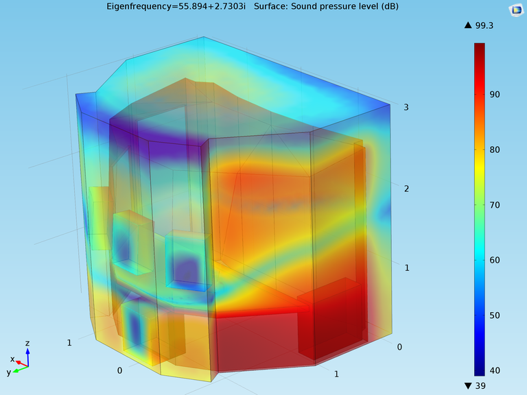
Ovviamente, uno dei punti chiave della progettazione dei piccoli ambienti è lo studio della distribuzione delle basse frequenze e quindi l’analisi modale. Questo è un capitolo piuttosto complesso e specialistico. In molti libri è scritto come ricavarsi la distribuzione delle onde stazionarie (e quindi lo studio dei massimi e dei minimi) per una sala rettangolare, e quindi come scegliere la sala rettangolare dalle dimensioni ottimali. In questi casi, purtroppo, le sale non sono né rettangolari, né tantomeno si può scegliere facilmente il rapporto dimensionale ottimale. Da un lato questo non è un grande problema, perché la quantità di assorbimento acustico presente in questi ambienti per ottenere i parametri in accordo con le linee guida AES, EBU, ITU etc. è molto consistente e questo aspetto fa sì che la scelta delle dimensioni ottimali sia un problema meno rilevante. Da un altro, è molto difficile simulare la distribuzione delle onde stazionarie in un ambiente “qualsiasi”, per due fattori, la geometria e l’impedenza delle pareti, che, pur essendo estremamente isolanti, non sono mai considerabili “pareti rigide”, soprattutto se si utilizzano sistemi a secco. Senza soffermarmi troppo su questo aspetto, posso dire che il metodo più pratico per affrontare questi problemi, è mediante l’utilizzo di un simulatore FEM (finite element method) come ad esempio Comsol Multiphysics, che, oltre alla simulazione, riesca anche ad eseguire ottimizzazioni, fornendo importanti informazioni sugli strati e la posizione di materiale fonoassorbente e la collocazione ottimale del punto d’ascolto.
Un altro aspetto fondamentale della progettazione di queste facility è l’isolamento tra sale adiacenti, solitamente collocate molto ravvicinate tra loro per ottimizzare gli spazi, ma che devono funzionare indipendentemente, senza ovviamente interazioni con la sala accanto e con gli ambienti circostanti. Le control-room spesso condividono vocal-booth per voice-over che sono spesso luoghi estremamente piccoli in cui bisogna mantenere un livello di isolamento elevatissimo, per evitare che la traccia registrata venga disturbata dalle immissioni sonore provenienti dalla sala adiacente o dai corridoi e dagli ambienti circostanti. Questo è un aspetto molto più semplice dell’acustica, rispetto a quella interna delle sale, ma è un elemento chiave perché determina la possibilità di utilizzare gli ambienti. Non basta scegliere la giusta stratigrafia delle partizioni, ma si deve porre molta attenzione ai dettagli di costruzione, ai supporti antivibranti per controsoffitti e pavimenti flottanti e soprattutto agli impianti di aerazione e di cablaggio audio, che spesso possono trasportare rumore da e verso le sale. Per la grande maggioranza di queste sale si utilizzano sistemi a secco fatte in cartongesso, fibrogesso, gomme di diverso tipo e materiali assorbenti, per le partizioni verticali e per i soffitti. Per quanto riguarda i pavimenti flottanti, il target è quello di costruire un efficace sistema “massa-molla” che dovrà avere come frequenza di risonanza almeno la metà della frequenza relativa alle vibrazioni immesse che si vogliono andare a smorzare. Per abbassare questa frequenza è necessario utilizzare massa, questo è il motivo per cui, oltre ai sistemi a secco formati da strati multilayer di MDF, cartongessi, sughero, gomme e lane minerali, si preferiscono sistemi in cemento posti su supporti antivibranti. Parlando invece della parte interna delle sale, oltre allo studio delle basse frequenze, un altro aspetto molto importante è l’interazione con le superfici rigide, che, ahimè, sono sempre presenti in una control room, basti pensare al banco e ai display. Anche se il punto d’ascolto è molto ravvicinato, e sembrerebbe molto semplice avere una risposta in frequenza flat al punto d’ascolto utilizzando uno studio monitor adeguato, questo non è affatto scontato, perché le superfici rigide sono estremamente ravvicinate ed è molto semplice che generino cancellazioni e comb filters sulla risposta in frequenza. Del resto, le sale devono essere oltre che acusticamente performanti, anche ergonomiche per poter lavorare anche in due persone (direttore del doppiaggio e fonico) che spesso entrano a malapena negli ambienti in questione. Per questi motivi, quando è possibile, si preferisce utilizzare la proiezione su uno schermo fonotrasparente (che non è così banale trovare... e purtroppo non lo è mai abbastanza!), piuttosto che un TV LCD che, oltre ad essere una superficie riflettente che spesso restituisce al punto d’ascolto brutte riflessioni soprattutto dai monitor surround, solitamente va ad ostruire la linea di fuoco della cassa centrale in un sistema 5.1. Il problema delle superfici riflettenti si ha anche per i diffusori. In effetti, i tradizionali diffusori a resto quadratico come i QRD o gli Skyline, a mio parere per questi ambienti non vanno bene, per diversi motivi: la distanza tra i punto d’ascolto e il diffusore non è sufficiente da riuscire a far sentire l’effetto della diffusione; anche se sono diffusori, com’è noto, non diffondono tutte le frequenze dello spettro, ed essendo creati con una grande superficie riflettente, possono per alcune frequenze creare dei problemi; sono dei dispositivi molto grandi e soprattutto profondi, e questo li rende difficilmente inseribili in queste sale.
Per gli studi di Fox International Channels a Hammersmith, London (UK) ho infatti preferito utilizzare un binary amplitude diffuser (basandomi sulle ricerche di E. C. Payne-Johnson, G. A. Gehring, and J. Angus – Improvements to Binary Amplitude Diffusers, Audio Engineering Society Convention Paper 7143) che è in pratica un dispositivo assorbitore-risonatore, costruito da un pannello forato basato su un algoritmo pseudorandom e posto davanti a un importante strato di materiale fonoassorbente, che in poco spazio permette, mediante un effetto di phase-shift, di fornire anche a distanze contenute, una buona diffusione sonora estesa su un range di frequenze molto più vasto di quello dell’accordatura di un diffusore a resto quadratico. L’ultimo aspetto fondamentale è la scelta e la collocazione dei monitor da studio. Riprendendo il discorso fatto nel mio articolo dello scorso anno “Monitors in a room” Resolution v13.3, anche per questi piccoli ambienti il flush mount può essere molto utile, perché elimina molti effetti di diffrazione e ottimizza il comportamento alle basse frequenze dei monitor. In questi casi, inoltre, è più facile inserire uno schermo di proiezione, tuttavia bisogna prestare molta attenzione al rivestimento del baffle (che per control room stereo solitamente preferisco rendere riflettente) perché il fronte non è l’unico punto dove sono presenti le sorgenti sonore, e spesso capita che l’interazione con i surround monitor sia estremamente problematica. In questi casi si preferisce renderlo comunque assorbente. Con tutte queste necessità, è evidente che il progetto non è più un tipico LEDE, Non-Environment etc. ma deve assumere dei tratti “nuovi”, adeguati per questo utilizzo specifico, e, purtroppo per l’acoustic designer, si tratta di qualcosa di diverso, da dover studiare, analizzare, simulare ed ottimizzare.
The last key aspect is choosing and placing the studio monitors. As discussed in my article Monitors in a room (Resolution V13.3), ush mounting can be really useful, even for small rooms as it eliminates many diffraction effects and improves the monitors’ low frequency output. With ush mounting it is also easier to insert a projection screen. However, you have to pay attention to the design of the baf e wall because the front wall is not the only location for sound sources as often the surround monitor interaction with the baffle wall in the front is problematic. In these cases it is preferable to finish the baffle wall with absorbent material. For stereo control rooms I usually prefer reflective finishes.
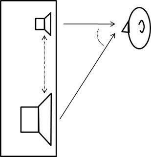
The studio monitor choice is challenging. In some applications 3-way monitors are needed, for example in postproduction for control of the midrange frequencies in voices. Then you have to pay attention to the distance from the listening position. Let me illustrate some of the factors affecting listening at close range and to help you understand if the setup is OK and why.
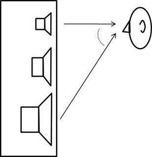
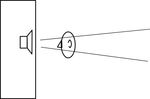
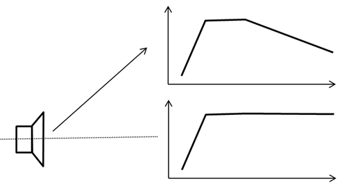
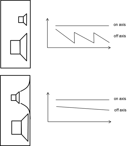
The Figures show how the relative listening direction becomes increasingly different for a listener when he approaches the monitor. This will increase problems with atness when the listener moves off-axis to some drivers (Figure 1); timing error between drivers particularly at the crossover frequencies; and the de nition of being on-axis becomes narrower when you approach the monitor (Figure 2). Driver directivity changes the frequency response in off-axis listening (Figure 3); the actual layout of the drivers on the front baf e can affect being more off-axis with certain drivers (Figure 4); when moving closer the direct sound to reverberation ratio changes so the in uence of reverberation goes down; and if there are diffraction effects in the monitor design, moving closer changes these in frequency, and their relative level compared to direct sound can change. Figure 5 shows the bene t of using a Directivity Control Waveguide. The DCW can maintain at frequency response off-axis and at close range can produce a more stable sound.
It is impossible to determine the minimum listening distance of a monitor by just looking at it as acoustical data and measurements are needed. Genelec 1238CFs were chosen for Fox International Channel UK Studios and these work at a range of 1.5m because the manufacturer has taken care of controlled directivity and minimised cabinet and other diffractions.
Case Study: beep! Studios, Rome – Gorilla room
This was the acoustic design of a 5.1 TV mixing room with a square area that was barely 9 sqm with the contractor Proaudio Consulting. The brief was challenging: they wanted top audio quality standards and unique aesthetics to meet the room’s name – it was used to host an ingest system called Gorilla and had to look like a jungle. The fundamental problem was to contain the annoying resonances of a square room. In a square room acoustic modes overlap creating very peaky maxima and minima and to minimise the effects an ‘old trick’ was used. We turn the room by 45° and the real improvement in this design is related to the front side of the monitoring system. Every corner in the room has its acoustic treatment with sound absorbing materials to give signi cant absorption at low frequencies. The front corner of the room has been closed with a 45° heavy multilayer structure with differing acoustic impedances. This is not possible with masonry, and MDF, plasterboard, and rubber were used.
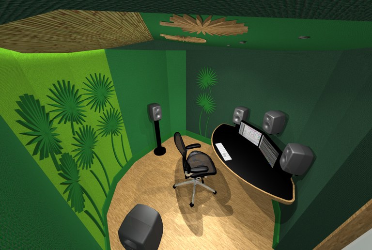
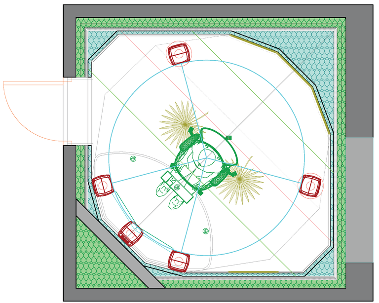
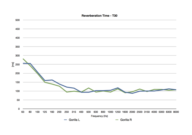
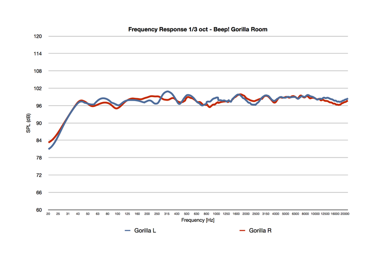
This wall structure, as well as dampening typical resonances of the square room, also serves to minimise the effects of phase cancellation of the LCR speaker system so typical with a conventional room corner. I mentioned this effect in last year’s article Monitors in a room (Resolution V13.3). Applying the ITU circle with surround monitor angles of 120°, all monitors are now close to walls and the monitor arrangement is perfectly integrated with the ro25o0m structure.
The small console table is designed to minimise re ection with a circular armrest. Another possible improvement would be to make the table top slightly tilted, to reflect sound away from the listening point, but in this case it would not be ergonomic because the table is also used for notes and scripts. Auto-calibration can help by compensating the remaining interactions that otherwise can not be removed.
Proaudio’s project manager wanted to deliver a unique-looking room and this led me in collaboration with Valentina Cardinali to design palm shaped acoustic diffusers and to use a bamboo cane nish for a panel at the back of the ceiling.
Case study: FOX International Channels UK, London
This project was for the isolation and acoustic design of two 5.1 TV mixing rooms, sharing an isobooth and a video postproduction room, all to be hosted in a barely 42sqm area. The contractor was again Proaudio Consulting. The brief was close to impossible -– top audio quality standards and branded aesthetics and we were provided with guidelines to follow that were many inches thick. At a rst glance this was an almost hopeless assignment, especially considering that the volume needed for soundproo ng partitions had to be included in this space. I worked with Alessandro Travaglini, Fox’s resident sound supervisor and engineer in Rome from the very beginning, who was our client’s appointed technical interface.
We created a binocular-shaped shell to host twin 5.1 control rooms sharing an isobooth between (the postproduction room was easier to locate), optimising the use of the available space to the centimetre and considering all the technical requirements (D-Command, projector and projection screen, cabinets, extended table-console, 5.1, 2.0 and soundbar audio systems) as well as the ergonomics.
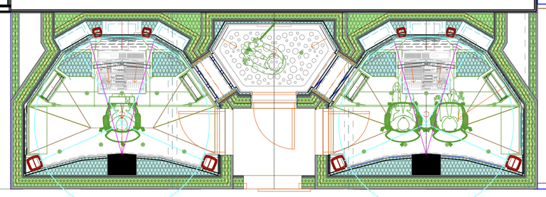
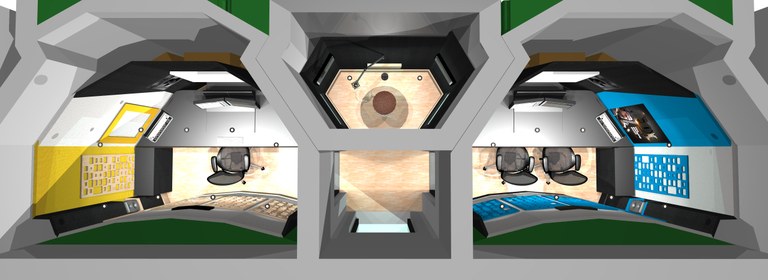
We chose a Genelec 5.1 audio system of three 1238CFs for LCR and two 8250As at the rear plus a 7270A subwoofer. This design was a great challenge and needed a careful study to understand if it was possible to insert 3-way monitors ush-mounted in such a small space. After a series of trial designs we noticed that the listening position was located about 1.5m from the monitors as the manufacturer’s minimum listening distance requirement and was enough to get a good listening experience. We rotated the DCWs because otherwise the tweeter would have been too high and would have been a problem for the projection screen placed in front of the monitors.
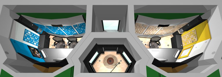
The front baffle wall is not only a technical element, but also a technical area for the cabling of the room. The baffle wall is partially covered and lled by damping material to avoid acoustic reflections of the surround speakers. At the back of the room there are the binary amplitude diffusers and absorbers I mentioned earlier, playing probably the most important role for creating the room acoustics.
The geometry of the side walls has been designed to not directly reflect audio waves to the listening position while creating a good view of the isobooth window. Another specular reflective surface was placed on the other side of the room to create symmetry with the window. This was used for the National Geographic rectangular logo and a Fox poster.
The ceiling has a thick absorbent layer and has reflective surfaces guiding waves coming from the front out towards the diffusers at the back, acting as a sort of geometrical ‘amplifier’ of the diffuser. The console was custom-designed to Travaglini’s concept and contained all the racks and workspace. For this reason the console has a very large surface and instead of tilting it I chose to cover specific areas with absorbing material to reduce first reflections from the L and R monitors. The reflections coming from the centre monitor are partially screened by the displays. This resulted in an extremely useful design. This project has been one of the most complicated I have ever dealt with but I considered it a challenge to overcome.
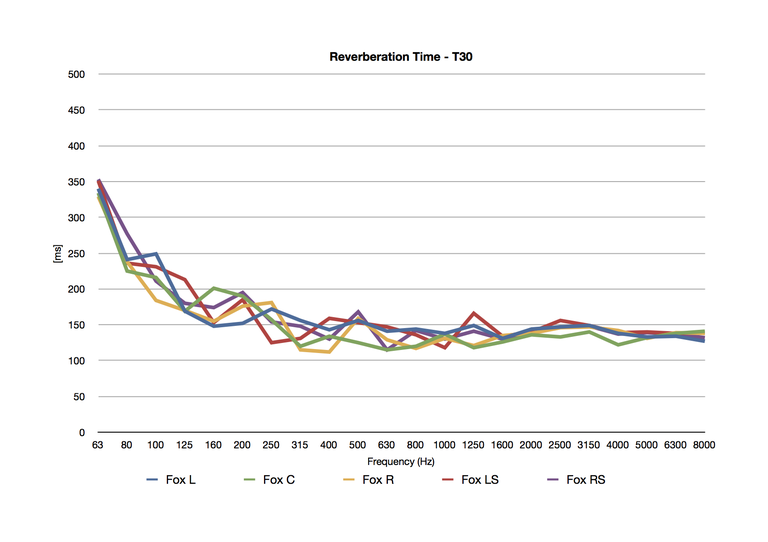
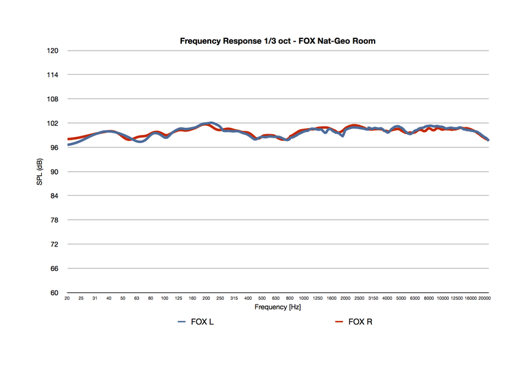
In conclusion, I’ve shown examples of how it is possible to build small control rooms for professional quality monitoring. Extreme care is needed at low frequencies and with acoustic reflections; a monitor auto-calibration system can reduce the inevitable remaining acoustic problems caused by reflections especially reflections from the console surface. However, I don’t want to be taken for an acoustician who prefers small rooms! Although these rooms sound very good and we are extremely proud of them, it is clear that working with traditionally sized rooms is much easier, the acoustic solutions are more natural and the performance results are higher. If you are not just looking at the acoustic parameters, this difference will be appreciated at the end of the work.
The next stage in the design of small monitoring rooms will surely be the inclusion of 3D immersive audio. Today there is no format that can be used in such small rooms as to-date only large mix theatres have these systems. But with the introduction of 3D audio in broadcast, for TV drama productions and sports events, the ITU recommendation for multichannel monitoring systems must be updated (or will need hybridisation) for systems such as Dolby Atmos and Auro-3D.
Footnote
Donato would like to thank his business partner Francesca Bianco, Proaudio Consulting’s project manager; Christophe Anet and Aki Mäkivirta (Genelec); Valentina Cardinali and Roberto Magalotti (B&C Speakers); Matt Ward (Spark + Rumble Ltd) and his friend Christopher Martinuzzi for reviewing the text.


