March 2016
Resolution Magazine
LF Analysis for studio design
As everyone knows, the most important problems to be solved in a control room, and in recording studios in general, are related to low frequencies. DONATO MASCI from Studio Sound Service, explains his approach.
1. Introduction
To understand low-frequency phenomena you must always remember that you are dealing with sound waves whose dimensions are comparable to those of the room, so if they could t ‘perfectly’ in the room they would resonate. For this reason, the range of the spectrum below 200Hz is usually called the ‘modal zone’ and is studied with wave acoustics.
In a typical control room, the low frequency reverberant eld is directly dependent on the resonance modes. In general, we are all used to seeing reverberation time charts in 1/3-octave bands, but if we could evaluate the modal decay times (MT60, reverberation of a single mode) at LFs we would notice that these perfectly determine the reverberation times. Even the high-frequency reverberation time depends on the room resonances, but these are a very high number so they cannot be treated in a discrete way only in a statistical way. This is the case in which we use simulations, such as ray tracing (which is the most common simulation method of acoustic CADs) and formulas as the Sabine law.
On the other hand, at low frequencies you cannot use statistics. To put it in physical terms the eld is ‘quantised’ — in other words the resonances are mostly isolated and distinguishable. Depending on the resonance, the sound energy (and therefore the pressure) is not uniform in the room and this fact is of great importance because it has a fundamental consequence -– the same sound-absorbing material, if placed at a point of maximum pressure, has better performance. It means that you cannot quantify the absorption if you do not know the position of the absorber with respect to room resonances.
In recording studio design it is therefore essential to precisely know the room resonances, and this is easy for rectangular rooms as there is an analytical formula that relates the resonance frequencies with the three spatial dimensions, but it is not trivial for all other geometries.
Alton Everest in Master Handbook of Acoustics talks about the non- rectangular room modes saying: ‘The acoustical bene t derived from the use of nonrectangular shapes in audio rooms is controversial. As Gilford noted, slanting the walls to avoid parallel surfaces does not remove timbral defects; it only makes them more dif cult to predict.’
And more: ‘The proportions of a rectangular room can be selected to eliminate, or at least greatly reduce degeneracies, while in the case of the nonrectangular room, a prior examination of degeneracies is dif cult. Making the sound eld asymmetrical by splaying walls introduces unpredictability in the design.’
Philip Newell (Recording Studio Design) says: ‘The effect of angling the walls of a room is only really bene cial in the reduction of utter-echo-related problems between hard surfaces at higher frequencies. Once a room is not perfectly rectangular, and does not have perfectly rigid walls, there are no formulae for accurately calculating the modes.’
And more: ‘(...) the degree of internal acoustic control which has been introduced into the rooms damps the modes to such a degree that the shapes of the isolation shells are largely unimportant.’
From these statements, all accurate and correct, we understand that, historically, non-rectangular rooms have always been regarded with a certain insecurity by the acoustic designers, probably because they actually did not have the right tools to analyse them.
Nowadays FEM (Finite Element Method) software is common and can be used to see the room modal resonances, to simulate the interaction of a sound source with the room, the frequency response at the listening point(s) and the absorber performances. Furthermore, with some of this software you can also make optimisations (for example, to choose the right amount of absorption or the best placement of the monitors and the listening positions) and, for simple cases, if you have previously measured the empty room reverberation time, you can try to estimate wall impedances.
Actually, the first problem I came up against when using this software (which is not designed for acoustics and therefore their libraries are not so useful) was to understand every single wall impedance, which determines the sound isolation but also the amount of energy that remains in the room and then resonates.
I have observed and verified significant changes in the acoustic field with different types of wall — a drywall system made with plasterboard makes substantial changes to the reverberation and modal distribution compared to a masonry or concrete wall. Another important thing is that when you introduce speci c absorption in the room, such as a resonator or a thick layer of porous material, the sound eld changes but in contrast to what you might imagine. Not only do the maxima and minima effects decrease but the resonances also have a frequency shift. These phenomena are easily seen with FEM analysis.
2.1 Flush mount – minimum and non minimum phase effects
The first results from a control room FEM analysis are the effects of ushmounting or not ushmounting the main monitors.
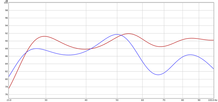
In the Figure 1 the red line is relative to the response at the listening position of big ushmounted monitors, the blue curve represents the case in which the monitor is not ushmounted. The difference is huge, the linearity is already suf cient for the ushmounted one. In the non- ushmounted trace there is a notable loss of sound energy around 35, 70 and 100Hz. So, with this method, we can nally see the non-minimum-phase effects caused by the monitors-room interaction, which I discussed in my previous articles (especially in Monitors in a room, Resolution V13.3.)
In this case, if you do not want to ushmount, the only way to save the response is to further distance the monitor from the back to bring down the notches below 85Hz and use a subwoofer with a crossover.
2.2 Bass-trap analysis
Another interesting thing to see is how the reverberation time changes in a room if you put a bass-trap on one side or in a corner.
I simulated the resonant modes in a room of an ideal size (Louden 1/1.4/1.9, that is, H = 3.4m, W = 4.76m, L = 6.46m) rst empty, then inserting a bass trap (a porous material parallel-piped 40cm x 40cm size) in the middle of the long side and then moving it to the corner.
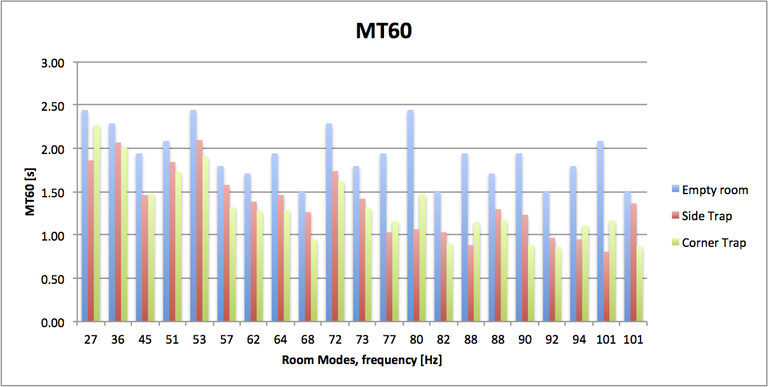
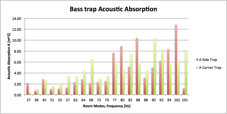
Figure 4 shows the single mode decay times (MT60, which you can compare with the reverberation time RT60 of the room) and you notice how the same bass trap works in very different ways in the two con gurations, giving different decay times. Figure 5 shows the absorption A [m2, metric sabin] of the same bass trap in two con gurations, frequency by frequency. For some resonance modes (especially longitudinal and transverse axial), the side trap is very powerful, but in general the corner trap works better and more homogeneously over the whole spectrum.
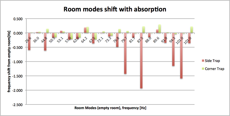
The last thing to note is that the room acoustic field is completely transformed even with the inclusion of a single bass trap –- it can be seen in Figure 3, but particularly in Figure 6, where the resonant mode frequency shifts are shown. When the absorption is equal to that of a control room, the modes change radically, they combine and degenerate. It is very dif cult indeed to recognise the same resonance mode by comparing pre- and post-treatment acoustic simulations.

One of the most frequently asked questions from students and colleagues is how do you know how much a bass-trap actually absorbs? From this analysis you can understand that you really cannot give an alpha coef cient to such a device because its performance is highly dependent on the room and the location where you place it. The only accurate evaluation you can do is with FEM software, and, in fact, it is not easy to nd the correct poro-acoustic model to simulate the behaviour of the absorbent material.
2.3 Rectangular VS non-rectangular rooms
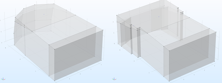
I am now going to look at the standing wave distribution in the room (room modes). I chose a room with ‘optimal dimensions’ again (the same Louden room) with another of identical size where the side walls are slanted in an x-axis symmetrical way. Figure 7 shows the mesh that the FEM software creates to do its processing. The mesh is made of tetrahedra and their size must be correlated to the wavelength being analysed. Since the low frequencies have long wavelengths our mesh is not so dense. The same software has many more problems analysing higher frequencies for which we use a ray-tracing method.
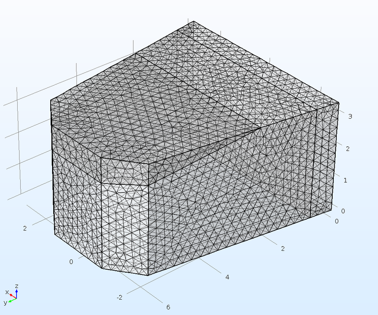
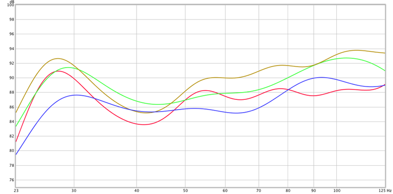
Figure 8 shows the frequency response of the two rooms in non-treated and treated con gurations (the treatment is a thick absorption on the back and on the ceiling, and in the case of the rectangular room, on the front corners). It is notable that the ‘Slanted room’ has more sound energy at LF and that treatment in both cases serves to minimise the cancellation to 40Hz and to linearise the response. For both rooms, even without knowing the reverberation time, which is obviously much longer when untreated, the treatment helps to linearise the frequency response and brings both to professional level (+/-3dB) minimising cancellations. It is wrong to think that an optimally-sized room already has a perfect FR without absorption, and from this comparison you can see how we can achieve similar or even better results with other room designs.
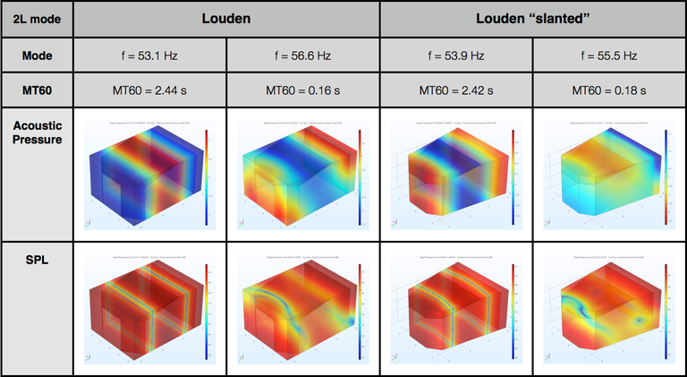
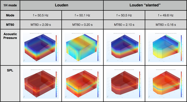
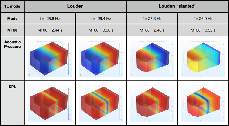
Figures 9, 10 and 11 show the sound pressure and the SPL of some of the rst resonance modes for the two rooms, in the treated and untreated con gurations. Note the reduction of modal decay time in the treated cases and the frequency shift of the resonance frequencies, but the most interesting result is that, in the treated con gurations, the sound pressure distribution is much more homogeneous. This is useful for design purposes where it is just important to minimise the effects of standing waves, decreasing the gap between the maximum and minimum point SPL.
These are some of the few modes that you can recognise for the treated rooms. In fact, even with this simple acoustic treatment, the modes completely degenerate and are destroyed above 50Hz, and then the sound pressure is distributed in an almost homogeneous way throughout the room.
3. Conclusions
On the basis of the above facts, it can be stated that FEM software is a truly valuable tool for acoustic design. It provides considerable support to designers on a part of the spectrum range (LF) that we could not have much certainty on until now — unless you precisely adopt a predetermined design that you know works from trial-and-error. The major innovation is that with these simulation methods you can build rooms with a good listening experience in unconventional situations while also studying alternatives and innovative acoustic treatments.
Footnote
Donato would like to thank Valentina Cardinali and Roberto Magalotti (B&C Speakers), and his assistant Cecilia Torracchi for useful discussions and thoughts.


